back to home
Attempting to repair a motherboard - Pt. 1
Gigabyte B450 Gaming X
Attempting to repair a motherboard
I AM NOT AN EXPERT IN REPAIRING ELECTRONICS
This is part 1 of a series of blogs that I'll write about my experiences with repairing this motherboard. I'll be posting as I go (who knows, I might even just end up scrapping it for metal :3).
Background/About the Board
I got the board for 7 euros on Ebay off some recycler in Vilnius, Lithuania. I wasn't looking for a cheap B450 board specifically, but any motherboard in general, as I wanted to build my own NAS/homelab.
As the name implies, the board contains a B450 chipset which supports AM4 cpus. The onboard graphics contains 1 HDMI output and 1 DVI-D output (as if we still live in the early 2000s).
The main reason why I got the board though was because of the 6 SATA ports on it, as I could then connect several hard drives for a large amount of storage while also potentially having RAID10 for performance and other things (look, I'm not a storage/server expert).
If you're interested about learning more about the board, you can click here
It begins...
Getting it out
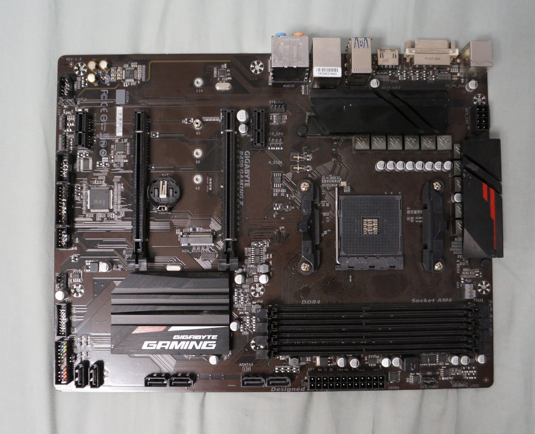
When I got the board out of its packaging, I noticed how dirty and dusty it was, and how there was a sticker with some number on it (which had to leave some paper and gunk behind after being peeled off).
Now, it also looks like on some connectors as if some of the pins are missing, but there were never there to begin with as there isn't a solder point on the rear of the board.
Front inspection
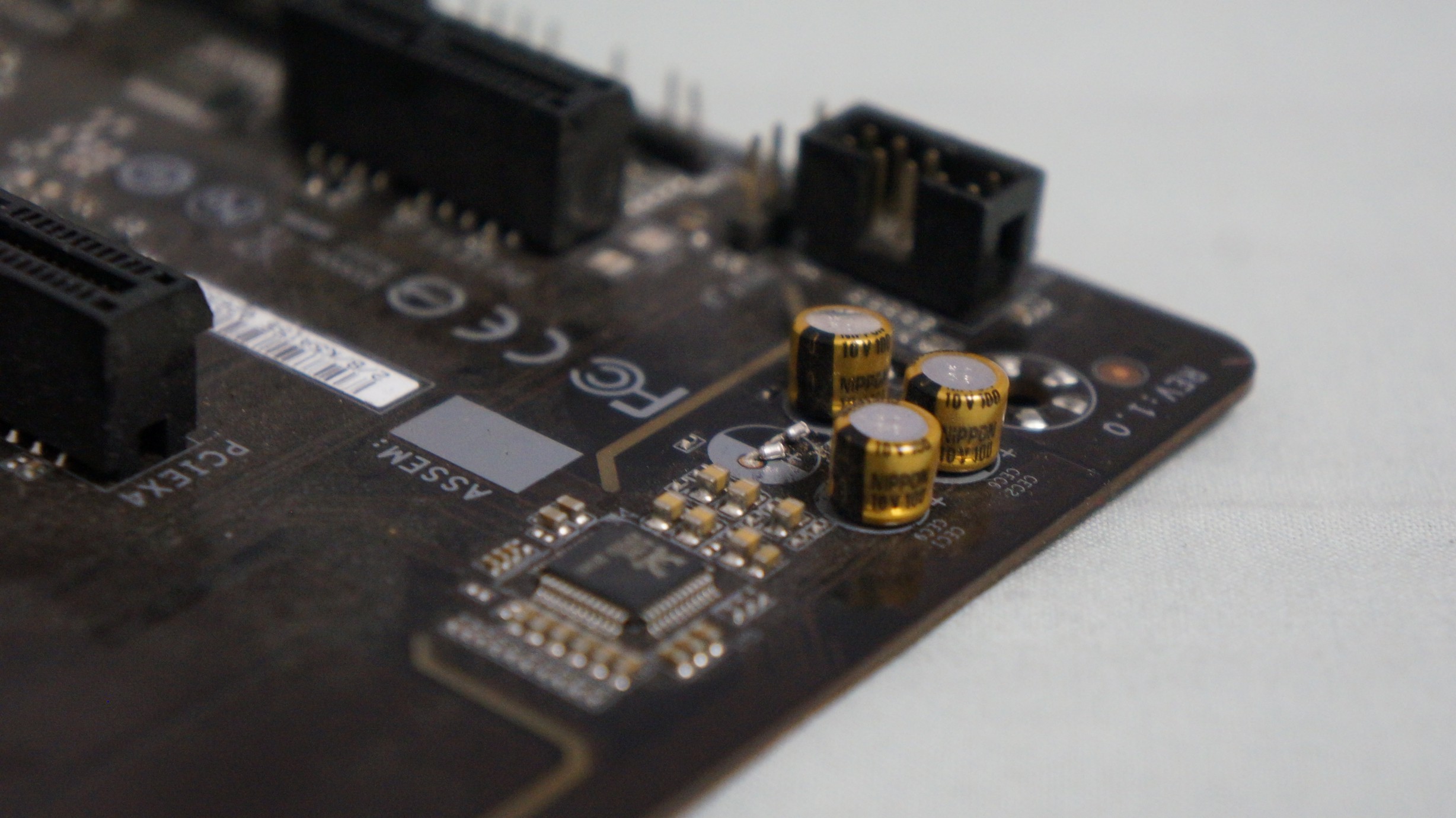
Inspecting closer only made it worse. At first, one of (what I believe is) the audio capacitors was completely misaligned and could be moved with a gentle push. Those gentle pushes then resulted in the entire capacitor coming out, meaning the job of removing (what was left of) the capacitor a bit harder as each pin would need to be pushed out when desoldering.
Rear inspection
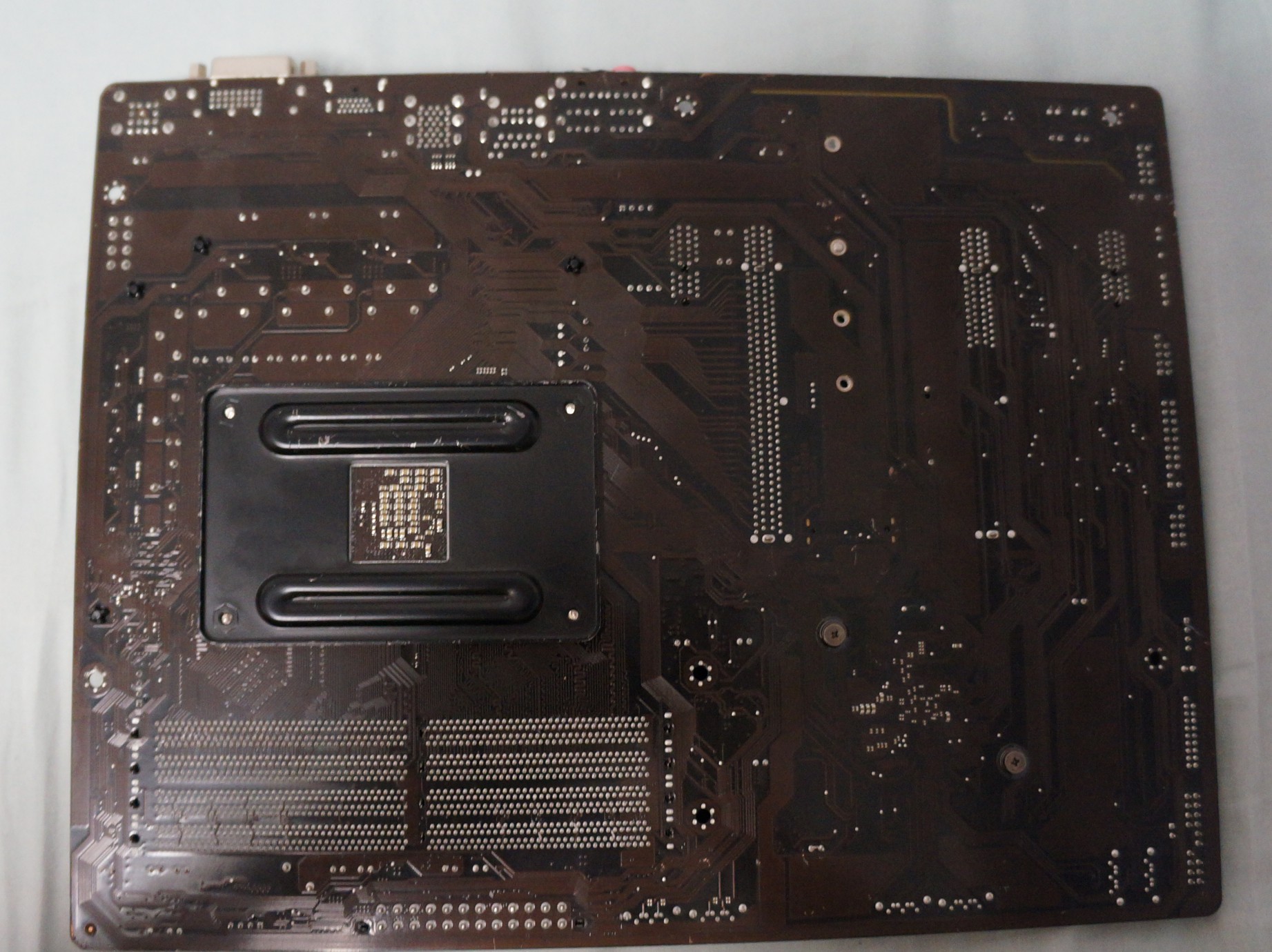
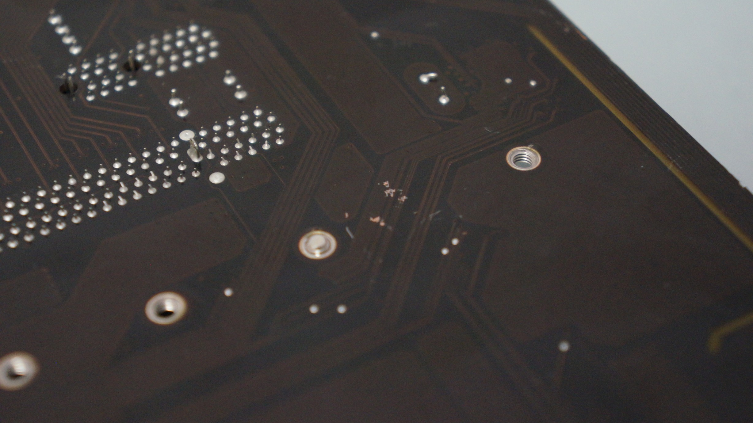
The rear of the board made me worried. Not only could I see many scratches, but there were quite a couple of areas where there was exposed copper. This could mean a cut connection on the board, leading to no power going to the destination.
Dealing with the capacitor
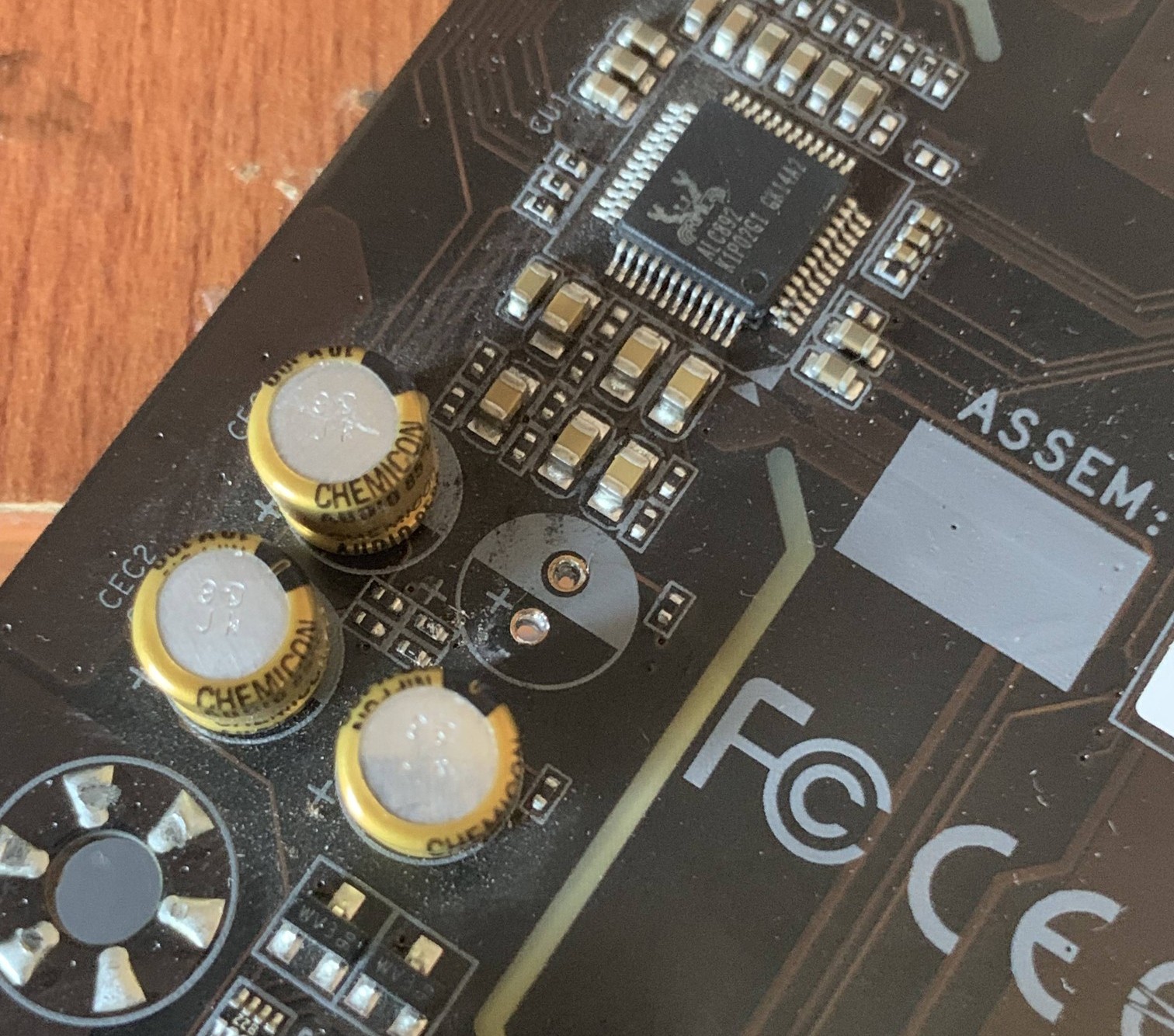
Being the idiot that I am, I put flux on and almost desoldered the wrong pins (thankfully the solder wasn't picked up by the braid).
I put my iron on one of the pinholes and pulled on the pin from the other side with a pair of wire cutters. The plan was that the solder will melt and the pin would be pulled out.
After both pins were out, I had another problem: solder covering the pinholes. To fix this, I put more flux on and used a thin soldering iron attachment (after it cooled down, of course) to pose through the hole and have the braid pick up the solder.
I unfortunately don't have a replacement capacitor at hand at the moment, so the board will have to have those empty holes until I can put another capacitor in.
